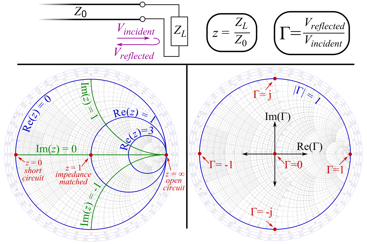
Reflection coefficients can be read directly from the chart as they are unit-less parameters. Once an answer is obtained through the graphical constructions described below, it is straightforward to convert between normalised impedance (or normalised admittance) and the corresponding unnormalized value by multiplying by the characteristic impedance (admittance). ONLINE SMITH CHART TOOL Frequency Frequency span ± Characteristic Impedance Permittivity e eff Impedance 50.0 + 0.00j Admittance 0.0200 + 0.00j Reflection Coefficient 0.00 + 0.00j Reflection Coefficient 0.00 0.00° VSWR 1. The most commonly used normalization impedance is 50 ohms. And the impedance values of added elements are: Option 1: (Ls0-(-1.22)1.22) Option 2: (Cs0-1.22-1. The Smith chart is composed of impedance (Z) or admittance (Y) circles of constant resistance, and curved lines, also called constant reactance segments (Z- and Y-). We will be using the Z-Smith chart only, however we will use the Y-circles as well while matching (you will have to imagine them). There are two Smith charts Y and Z (admittance and resistance).

Normalised scaling allows the Smith chart to be used for problems involving any characteristic or system impedance which is represented by the center point of the chart. 6 Type 1 impedance matching, Step 1 & Step 2. However, you can set the impedance to anything you want, as long as the source and load at any given node are equal (figure 2). These are often known as the Z, Y and YZ Smith charts respectively. The Smith chart is plotted on the complex reflection coefficient plane in two dimensions and is scaled in normalised impedance (the most common), normalised admittance or both, using different colours to distinguish between them.


 0 kommentar(er)
